
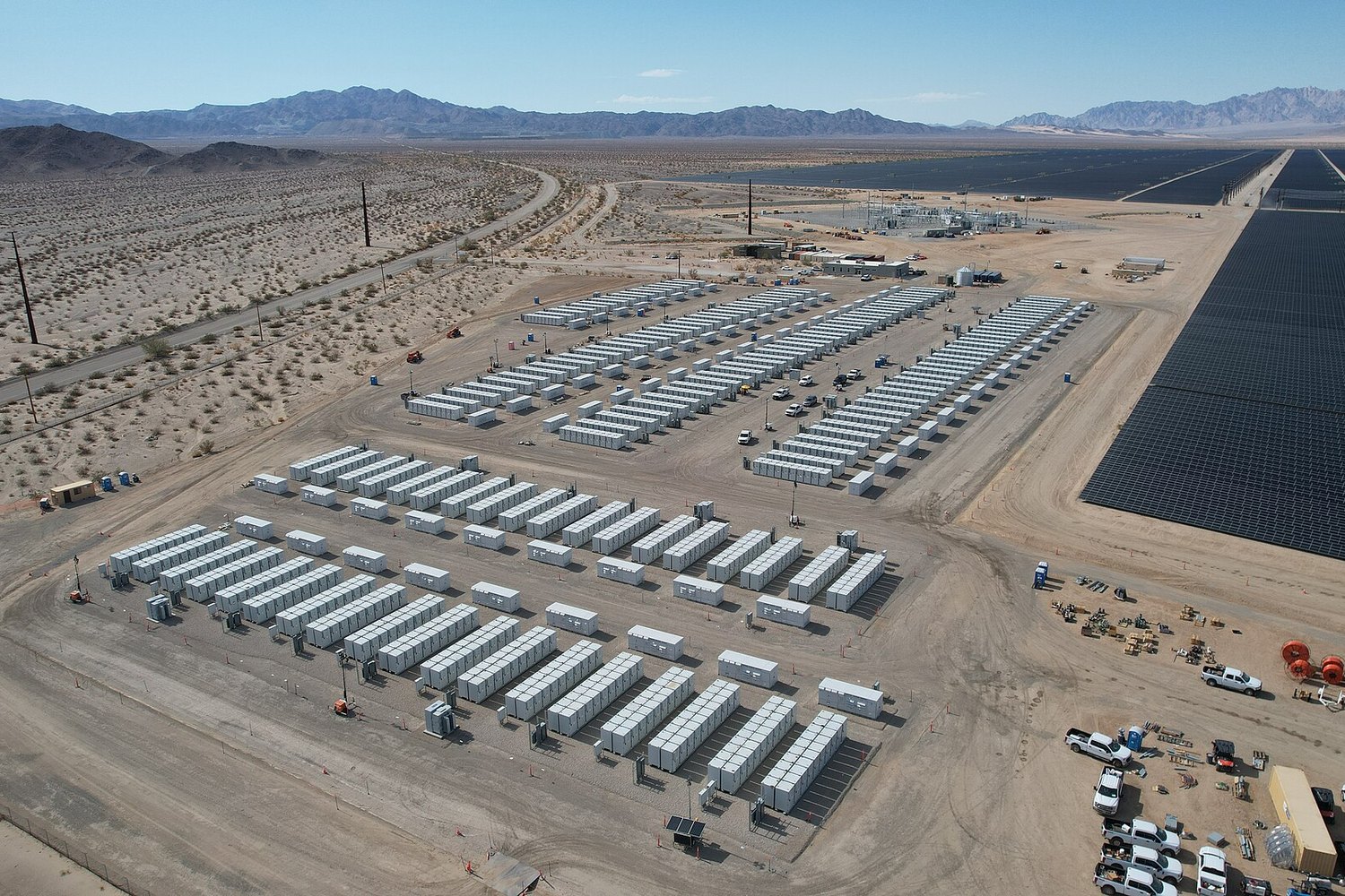
Commercial solar-plus-storage is designed as one system by sizing the battery to the demand-charge and time-of-use problem first, choosing DC or AC coupling, and drawing both power sources on a single electrical single-line diagram that the utility and the plan reviewer will read together. The battery is not an add-on. It shares the inverters, the point of interconnection, and the permit set with the array, so the electrical design has to represent both from the start. Tools like PVComplete's PVCAD produce the layout and the single-line diagram with the storage equipment in the library, and Enact models the array, the battery, and the resulting savings against the same load profile. Size the storage to the load shape and the tariff, then let the electrical design and interconnection follow.
Key takeaways
- A commercial battery shares the array's inverters, wiring, and interconnection, so it has to be sized and drawn as part of the same electrical design rather than added after the solar is finished.
- Storage is sized to the demand-charge and time-of-use problem the building has, which means the battery's power rating and energy capacity come from the load shape, not from a rule of thumb tied to array size.
- DC-coupled and AC-coupled architectures split the design in two directions, and the choice changes the inverter count, the retrofit path, and how the single-line diagram is drawn.
- The single-line diagram has to show both power sources, the power-conversion equipment, and the point of interconnection, because that is the document the utility and the plan reviewer evaluate.
- All production, savings, and payback figures for a combined system are modeled estimates tied to stated assumptions, and the federal ITC and depreciation now apply to qualifying standalone and paired storage.
- Why Solar and Storage Get Designed as One System
- What the Design Software Needs Before You Start
- Sizing the Battery to the Demand and Time-of-Use Problem
- DC-Coupled vs AC-Coupled Architecture
- Design Approaches and Coupling Options Compared
- Electrical Design and the Single-Line Diagram
- The Equipment Library and Why It Decides Design Speed
- Interconnection and the Utility's View of Storage
- From Design to Permit and Construction Set
- Where Combined Solar-Plus-Storage Design Goes Wrong
- How to Evaluate Solar-Plus-Storage Design Software
- Carrying the Combined System Through One Workflow
Why Solar and Storage Get Designed as One System
A common failure on commercial projects looks like this. The solar layout is done, the production model is signed off, and then the client's finance team asks what the battery does for the demand charges. Now the storage gets priced as a bolt-on, a battery sized by gut feel and wired into a design that was never drawn to hold it. The interconnection application gets amended. The single-line diagram gets marked up. The reviewer sends it back.
The reason is simple. A battery is not an accessory hung off a finished array. It is a second power source that shares the same inverters or inverter bus, the same point of common coupling, the same interconnection agreement, and the same permit set. When you add storage after the fact, you are redesigning the electrical system, not appending to it. The parts that change are exactly the parts that are expensive to change late.
So a combined system is designed as one object from the first decision. You size the battery to the problem the building actually has, pick the coupling architecture, and draw both sources on one single-line diagram before anything goes to the utility. The array and the battery answer different questions on the bill, and only a design that models them together can show which kilowatt-hours the solar offsets and which kilowatts the battery shaves. The U.S. Energy Information Administration explains how commercial prices stack energy, capacity, and delivery costs, and solar and storage attack different layers of that stack.
What the Design Software Needs Before You Start
A combined design needs everything a solar-only sizing needs, plus the inputs that tell the battery what job to do. Chasing these late is where paired projects stall, so pull the full set before placing a module or a battery.
- Twelve months of interval-load data at 15-minute resolution, which shows both the daytime shape the array matches and the peaks the battery has to shave.
- The full rate schedule, broken into the energy charge, the demand charge in dollars per kilowatt, and any time-of-use periods and seasonal windows.
- The monthly billed demand peaks and the hour each one lands, since an evening peak is a storage problem and a midday peak may not be.
- The customer's goal stated as a number: a demand-charge ceiling, a target offset, a backup-runtime requirement for critical loads, or a return threshold.
- Any backup or resilience need, including which circuits must ride through an outage and for how long, because that sizes energy capacity differently than bill savings does.
- Roof or ground area and condition, plus a location for the battery and its power-conversion equipment with the clearances the code requires.
- The service and transformer rating and the utility's interconnection and export rules, which cap both the array and the battery discharge.
- The inverter and battery brands the installer stocks, so the equipment library in the design tool matches what will actually get ordered.
- Planned load changes such as EV charging or added refrigeration that will move the peak the battery is being sized against.
Sizing the Battery to the Demand and Time-of-Use Problem
Solar is sized to energy. Storage is sized to power and timing. A battery has two numbers that matter, its power rating in kilowatts and its energy capacity in kilowatt-hours, and the load shape sets both. The power rating has to be large enough to cover the gap between the peak and whatever the array is contributing at that moment. The energy capacity has to be large enough to hold that discharge for the full width of the peak window without running empty.
Read the interval data for the shape of the monthly peak. A sharp 20-minute spike needs power but little energy. A broad three-hour evening plateau needs energy more than raw power. Size the kilowatts to the height of the gap and the kilowatt-hours to the area under it, then confirm the battery can recharge from the array or off-peak grid before the next peak arrives. This is dispatch, and it is the part a spreadsheet cannot honestly fake.
Under time-of-use rates, the battery earns a second job, moving midday solar into the priced afternoon and evening window instead of exporting it cheap. California's net billing tariff is the clearest example of why this matters, since export is now worth far less than self-consumption and storage is what captures the difference. Model the dispatch across a full year, because a battery sized for a summer peak may sit idle in winter or run short in a season you did not check. Treat every savings figure as a modeled estimate tied to the dispatch assumptions you stated.
DC-Coupled vs AC-Coupled Architecture
The first real design fork is how the battery connects to the array, and it changes almost everything downstream. In a DC-coupled system, the solar and the battery share a single hybrid inverter and meet on the DC side before conversion. In an AC-coupled system, the solar has its own inverter, the battery has its own, and the two meet on the AC side after each has converted independently.
DC coupling tends to be more efficient for new construction, because solar energy headed for the battery is converted once instead of twice, and it can capture clipped production that an AC inverter would have thrown away. It usually means fewer inverters and a tighter equipment count. The tradeoff is that the solar and storage are more tightly bound, which makes a DC-coupled design less forgiving to resize or expand later.
AC coupling is the natural fit for retrofits, where an array already exists with its own inverter and the battery is added alongside it. It is more flexible, since the two systems can be sized and serviced independently, and it scales in steps. The cost is a second round of conversion losses and a higher component count. On the single-line diagram these look like two different systems, and the design tool has to represent both correctly, including where the metering and the point of interconnection sit relative to each inverter. Picking the architecture early is what keeps the electrical design from being redrawn twice.
Design Approaches and Coupling Options Compared
The table below sets the main design approaches side by side on the dimensions that actually decide a commercial project, from coupling choice to the electrical deliverable each one produces.
| Approach / option | Best fit | Inverter and conversion | Electrical deliverable |
|---|---|---|---|
| DC-coupled, hybrid inverter | New-build solar-plus-storage on one design | One conversion, fewer inverters, captures clipped DC | Single-line diagram with one hybrid inverter and the battery on the DC bus |
| AC-coupled, separate inverters | Adding storage to an existing or separately phased array | Two conversions, independent sizing and service | Single-line diagram showing both inverters and the shared point of interconnection |
| Standalone storage (no new solar) | Demand-charge or backup only | Battery inverter alone, charged from grid or existing array | Single-line diagram for the battery, interconnection, and transfer equipment |
| Spreadsheet plus separate CAD | Teams piecing tools together | Depends on manual entry, drift between files | Diagram drawn by hand, reconciled against a separate model |
| PVComplete PVSketch | Fast sales layout and proposal with a permit package | Modeled from the layout, carried to engineering | Permit package including a single-line diagram and site plan |
| PVComplete PVCAD | Detailed engineering, layout, and electrical design | Modeled in AutoCAD with an equipment library for inverters and storage | Construction and permit sets with a detailed electrical single-line diagram |
| Enact design and proposals | Sizing, savings, and the financial model for solar and battery | Array and battery modeled against one load profile | Proposal and savings model tied to the engineered system |
Electrical Design and the Single-Line Diagram
The single-line diagram is the heart of a combined design, and it is the document the utility and the authority having jurisdiction actually read. For solar alone it is already detailed. Add storage and it has to show a second source, the battery's power-conversion equipment, the disconnects and overcurrent protection on both sides, the metering, and the exact point where everything ties into the service. Get the one-line wrong and the project does not get approved, no matter how good the layout looks.
Storage brings electrical rules that solar-only designs never touch. Battery energy storage systems carry their own requirements in the National Electrical Code and related fire standards, covering disconnecting means, working clearances, ventilation, and labeling, and the National Fire Protection Association maintains the NEC as NFPA 70 along with the storage-specific provisions a reviewer will check. A design tool that understands storage places these elements for you instead of leaving the engineer to hand-draw them.
The National Renewable Energy Laboratory notes that modeling a paired photovoltaic and battery system means simulating how the battery charges and discharges against the building's load and rate structure across the year, not treating the storage as a fixed credit, because its value depends entirely on when it operates.
National Renewable Energy Laboratory, System Advisor Model
This is why the electrical design and the dispatch model cannot live in separate worlds. The one-line defines what is physically wired, and the dispatch model defines what that wiring does hour by hour. A tool like PVComplete's PVCAD produces the layout and the electrical single-line diagram in the same AutoCAD environment the engineering already runs in, so the battery appears on the drawing and in the equipment schedule rather than being added as a note after the fact.
The Equipment Library and Why It Decides Design Speed
A combined design is only as fast as the equipment library behind it. Every module, inverter, battery, and balance-of-system part carries electrical characteristics that drive string sizing, conductor selection, overcurrent protection, and the symbols on the one-line. Enter those by hand for every job and the design slows to the pace of datasheet lookups, and each manual entry is a chance to transpose a number that a plan reviewer will catch.
A design tool with a real equipment library holds the inverters and storage products the installer actually uses, with their ratings already loaded, so the engineer selects a part instead of typing its specifications. For solar-plus-storage this matters more than for solar alone, because the battery and its power-conversion equipment add a whole class of components, and a DC-coupled hybrid inverter behaves differently on the drawing than an AC-coupled pair. PVCAD carries an equipment library in its AutoCAD environment so the storage hardware is a library selection, and the single-line diagram and equipment schedule update from that selection rather than from a separate spreadsheet.
The payoff is consistency. When the library drives the drawing, the system you engineer is the system that gets ordered and built, and the quantities on the plan set match the bill of materials. That matters on a commercial deal where a reviewer, a finance team, and a procurement manager all read the same documents and expect the numbers to agree. Enact's integrations across many inverter and battery manufacturers, including names such as Enphase, SolarEdge, Tesla Powerwall, Sol-Ark, and FranklinWH, are the same logic applied to the sizing and proposal side, keeping the modeled system aligned with real hardware.
Interconnection and the Utility's View of Storage
A utility does not see a battery the way a customer does. Where the owner sees bill savings, the utility sees a device that can both pull from and push onto the grid, and it regulates that two-way behavior carefully. The interconnection application for a paired system has to state the battery's power rating, whether and how much it can export, and what controls prevent it from backfeeding beyond the approved limit. These answers come straight off the single-line diagram and the inverter settings, which is another reason the electrical design has to be settled before the application goes in.
Many utilities treat a non-exporting or export-limited battery differently from one allowed to sell energy back, and the design can use that. A system configured to serve only on-site load and shave demand may clear a faster interconnection path than one seeking full export rights, because it poses less risk to the distribution network. The design software should let you set and document that export limit so the application matches the hardware. Where a project does export, the value of that export depends on the tariff, and under structures like California's net billing tariff the economics push hard toward self-consumption and storage over sending energy to the grid.
Federal programs have made storage easier to justify on the interconnection and financial side at once. The Solar Energy Industries Association describes the Investment Tax Credit as now reaching qualifying standalone and paired storage, and treats accelerated depreciation of solar property as a separate benefit, both of which change the return on a battery that the utility application and the model have to reflect consistently.
From Design to Permit and Construction Set
The design work turns into a stack of documents, and for a combined system that stack is larger than for solar alone. A permit package has to carry the site plan, the array and battery layout, the single-line diagram showing both sources, the attachment and structural details, the fire-safety plan with the storage clearances and labeling, and the datasheets and certifications for every piece of equipment. Each of those has to agree with the others, because a reviewer reads them as one set and sends the whole package back when the battery on the layout does not match the battery on the one-line.
This is where generating the set from the model instead of assembling it by hand pays off. PVComplete's PVSketch produces a one-click permit package, including the project summary, site plan, single-line diagram, safety labels, attachment plans, and datasheets, from the layout itself, and PVCAD produces the detailed permit and construction sets from the engineered design. Because the storage is already in the model, it flows into every sheet rather than being penciled into some and forgotten on others.
Keeping the documents generated from one source also shortens the back-and-forth. Automated review tools such as the Department of Energy's work to speed up solar permitting reward clean, consistent submissions, and a storage project with a coherent set of drawings moves faster through a jurisdiction than one stitched together from mismatched files.
Where Combined Solar-Plus-Storage Design Goes Wrong
The same mistakes recur on paired projects, and almost all of them trace back to treating the battery as an afterthought rather than part of the system.
Designing the solar first and the storage later. Adding a battery to a finished array means redoing the inverter plan, the one-line, and often the interconnection application, which is slow and expensive at that stage.
Sizing the battery by a rule of thumb. A percentage of array size tells you nothing about the demand peak or the backup runtime, which are the numbers that actually set the battery's power and energy ratings.
Choosing coupling by habit instead of by case. Defaulting to AC coupling on new construction can leave efficiency on the table, and forcing DC coupling onto a retrofit can mean replacing an inverter that did not need to go.
Drawing a one-line that hides the battery. A single-line diagram that does not clearly show the second source, its protection, and the point of interconnection gets rejected, and storage carries code requirements solar alone never raises.
Modeling storage as a flat credit. A battery's value depends on when it charges and discharges, so a model that assumes a fixed monthly saving instead of simulating dispatch across the year will not survive a finance review.
Setting the export limit and the hardware apart. When the interconnection application claims a limit the inverter settings do not enforce, the utility catches it, and the project waits for a corrected submission.
Letting the model and the drawings drift. When the savings model, the layout, and the permit set come from different files, the battery on one does not match the battery on another, and the whole package bounces.
How to Evaluate Solar-Plus-Storage Design Software
Not every tool that places solar modules can honestly design a paired system. Use this checklist to test whether a platform is built for combined solar-plus-storage or just able to add a battery as an icon.
- It sizes the battery from interval-load data and the tariff, not from a ratio to the array, and reports power and energy ratings separately.
- It simulates battery dispatch across a full year against the load and rate structure, the way the NREL System Advisor Model treats a paired system, rather than applying a flat monthly credit.
- It supports both DC-coupled and AC-coupled architectures and represents each correctly on the single-line diagram.
- It produces an electrical single-line diagram that shows both power sources, the power-conversion equipment, the disconnects and protection, and the point of interconnection.
- It carries an equipment library with the inverters and storage products you actually install, so parts are selected rather than typed.
- It lets you set and document an export limit that matches the inverter settings for the interconnection application.
- It generates the permit and construction set from the same model, so the battery appears consistently on every sheet.
- It connects the engineered system to a savings and financial model, including the ITC and depreciation, without re-entering the design by hand.
- It keeps the sales layout, the engineering, and the proposal on one model so the system you design is the system you sell.
Carrying the Combined System Through One Workflow
A paired system touches sizing, dispatch modeling, electrical design, permitting, interconnection, and finance, and it breaks at every handoff between separate tools. The battery sized in a spreadsheet, drawn in a CAD file, and modeled in a third program rarely stays the same battery across all three, and on a commercial deal the gap between the system designed and the system proposed is where trust and margin leak out.
Keeping the chain on one model is what closes that gap. PVComplete's PVSketch lets sales start a fast layout and proposal with a permit package, and the handoff into PVCAD lets engineering finish the detailed layout and the electrical single-line diagram with the storage in the equipment library, producing the permit and construction sets from the same design. PVCAD is desktop software that runs on AutoCAD and needs that license, which is a real cost, and in return it gives the electrical detail a commercial reviewer expects. Enact carries the other half, modeling the array and the battery against one load profile and turning the engineered system into the commercial savings and proposal the customer signs through the same design and proposal platform. Because the load, the dispatch, the drawing, and the financial model share one system, the solar-plus-storage you engineer is the one you interconnect and the one you sell.
Frequently asked questions
How do you design a commercial solar-plus-storage system?
You design it as one system: size the battery to the demand-charge and time-of-use problem, choose DC or AC coupling, and draw both sources on a single electrical single-line diagram before the interconnection application. The battery shares the inverters, the point of interconnection, and the permit set with the array, so the electrical design has to represent both from the start. Modeling the dispatch across the year, the way the NREL System Advisor Model treats a paired system, is what makes the savings credible.
What software is used for solar and battery storage electrical design?
For detailed electrical design, a CAD-based tool that produces a single-line diagram with both the array and the battery is the standard, and PVComplete's PVCAD does this in AutoCAD with an equipment library for inverters and storage. It generates the layout, the electrical single-line diagram, and the permit and construction sets from one model. The sales layout and proposal can start in PVSketch and hand off to engineering. See PVComplete for how the layout and electrical design connect.
What is the difference between DC-coupled and AC-coupled storage?
DC-coupled storage shares a single hybrid inverter with the array and converts energy once, while AC-coupled storage uses separate inverters for the solar and the battery and converts twice. DC coupling is usually more efficient for new construction and captures clipped solar, and AC coupling is more flexible for adding a battery to an existing array. The choice changes the inverter count and how the single-line diagram is drawn. Enact models either architecture against the load, as shown in its commercial tools.
How is a battery sized for a commercial solar project?
A battery is sized from the load shape and the tariff, with its power rating set by the height of the demand peak and its energy capacity set by how long that peak lasts. A sharp spike needs power, a long evening plateau needs energy, and backup requirements can change the capacity again. This has to be read from 15-minute interval data, and the dispatch simulated across the year so the battery does not run short in a season you did not check. The savings depend on the rate structure the battery operates under.
Does the single-line diagram change when you add a battery?
Yes, substantially. The single-line diagram has to show the battery as a second power source, its power-conversion equipment, the disconnects and overcurrent protection on both sides, the metering, and the point of interconnection, and storage carries code requirements that solar alone does not. The National Fire Protection Association maintains the NEC as NFPA 70 with storage-specific provisions a reviewer will check, which is why the electrical design tool should place these elements rather than leave them hand-drawn.
Does the federal tax credit apply to commercial battery storage?
Qualifying standalone and paired storage can reach the commercial Investment Tax Credit, and accelerated depreciation applies to eligible solar property as a separate benefit. Both change the return on a battery and have to be reflected consistently in the savings model and the proposal. The Solar Energy Industries Association describes the ITC and treats depreciation of solar energy property as a distinct mechanism. Treat every resulting return figure as a modeled estimate tied to stated assumptions.
Sources
- NREL - System Advisor Model (SAM)
- EIA - Electricity prices and factors affecting prices
- CPUC - Net Billing Tariff
- NFPA 70 - National Electrical Code
- DOE - Streamlining solar permitting with SolarAPP
- SEIA - Solar Investment Tax Credit (ITC)
- SEIA - Depreciation of Solar Energy Property
- PVComplete - PVSketch and PVCAD design software
- Enact - Commercial solar solutions
See your real numbers
Enact builds proposals from your actual roof and utility data — so the savings you see are the savings you get. Get a free, no-pressure design.
Get a Free Solar Proposal